
Version 3.0 has been released!
www.livesectional.com
I spent a good couple of months working on streamlining this process so my fellow pilots can quickly get one of these fun live sectional maps up and running at their home, flight club, local airport, office, or all of the above. 🙂 In this post you’ll find a detailed shopping list, step by step directions as well as detailed videos walking you through each step of the process. If you end up building one of these I’d love a picture of your finished project. Also I need to send out a huge thank you to Mark Harris who really dove into the code and helped me bring all these new features in to version 2. Its collaboration like this that really makes the projects a reality.
Components – Link to Amazon Shopping list of basic electronic components. Full list below
- Raspberry Pi
- MicroSD Card
- LED’s (String of 50) You may need two depending on the number of airports in your project.
- Bread Board
- Jumper Wires
- 1N4001G Diode
- Power Adapter You’ll need one for every two strings of lights.
- Sectional Options
- Download a Sectional to print (FAA Free) or Purchase Aviation Wall Maps $$$
- Upload sectionals to PosterPrtintFactory (54×36 $85)
- Another printing option ~$50 (example size 44” w x 30” H)
- ⅜ inch Grommets
- Hot Glue Gun
- Particle Board
- 3M Spray Glue
- 3/8″ Leather/hole punch (Something Like This)
- 1×2 Pine Board (to create a spacer behind the particle board)
- New small V2 Pi3b+ Compatable (8gb sd card) Fully preconfigured Image File –––
- https://etcher.io Software to copy the img file you just downloaded to your blank MicroSD card.
- User: pi (username in the software)
- Password: livesectional
- Includes support for a power off button
- Includes support for a light sensor to dim the LEDs in a dark room
- Includes support for Lightning and High Wind Blinking of LEDs.
- Includes LED’s turn off when Pi shuts down or reboots.
- Updated metar.py file
- Original Source Code For those of you who don’t need this guide or extra features.
Steps
- Equipment Test
- Getting the Map On the Board and Board Preparation
- Configuring the Scripts for your Airports
- Wiring Everything Up
- Enjoy
- Consider throwing a couple bucks my way 🙂 paypal.me/WilliamBrysonIII
- Get stuck? Email me
Step 1: Equipment Test
During this process I had to switch out LED brands after sending one back and trying a replacement of the first brand. The reason we start with this on the how-to is just to be sure you have all working components before you start gluing things.
So lets get your Pi set up first, without changing out the airports file as you’ll need to tweak that once you actually glue in the LED’s.
First thing you’ll want to do is download the preconfigured img. This is the operating system and live sectional scripts for the Pi.
Full Pre-configured V2 Live Sectional Pi Image File (700 MB Download – Now supports 8 GB Micro SD Cards)
- User: pi
- Pass: livesectional
Next install https://etcher.io Software to copy the img file you just downloaded to your blank MicroSD card.
This image below shows the basic steps. Select the file livesectionalsm.img.zip that you downloaded, plug your MicroSD card into your computer using a card reader or MicroSD to SD card adapter Select that as your drive, and then click the flash. This will set the microSD card up for you. When that finishes take the MicroSD card out of your computer and plug it into the Pi
Basic Configuration
Plug your Pi into an HDMI cable plugged into you TV. Plug in a wired keyboard into one of the Pi’s USB ports, and plug it into power using the power adapter that came with the Pi.
When the Pi boots up it will come up to the command line prompt.
pi@LiveSectional:~ $
If this doesn’t show up, try hitting the return key on your keyboard.
This is the command prompt. It is where you can start entering commands to the Pi. I have set up the image you are using to automatically log you into the pi.
Let’s start with getting your PI connected to your wifi and changing the login passwords for the pi (Not required).
Type in the following command…
sudo raspi-config
Press the return key.
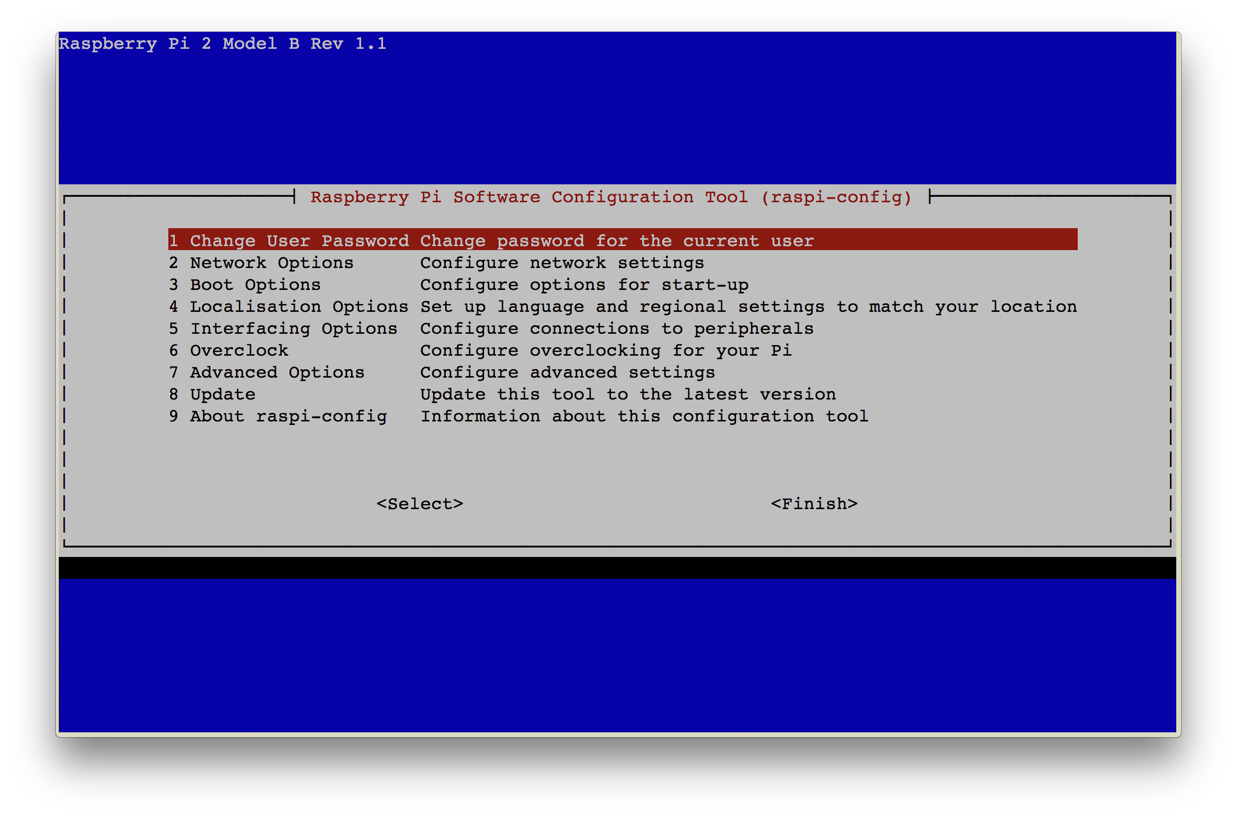
This will bring up a graphical configuration window. You’ll need to use the arrow keys on your keyboard to navigate this window.
To change the login password (Not necessary) make sure “Change User Password” is highlighted as shown below, and hit return on your keyboard.
This will return you back to the command prompt and it will tell you to type in a new password.
Type in your new password and hit the return key on your keyboard.
It will ask you to retype the password to confirm it.
Type in your new password again and then hit the return key on your keyboard.
Now to get your Pi connected to your wifi network.
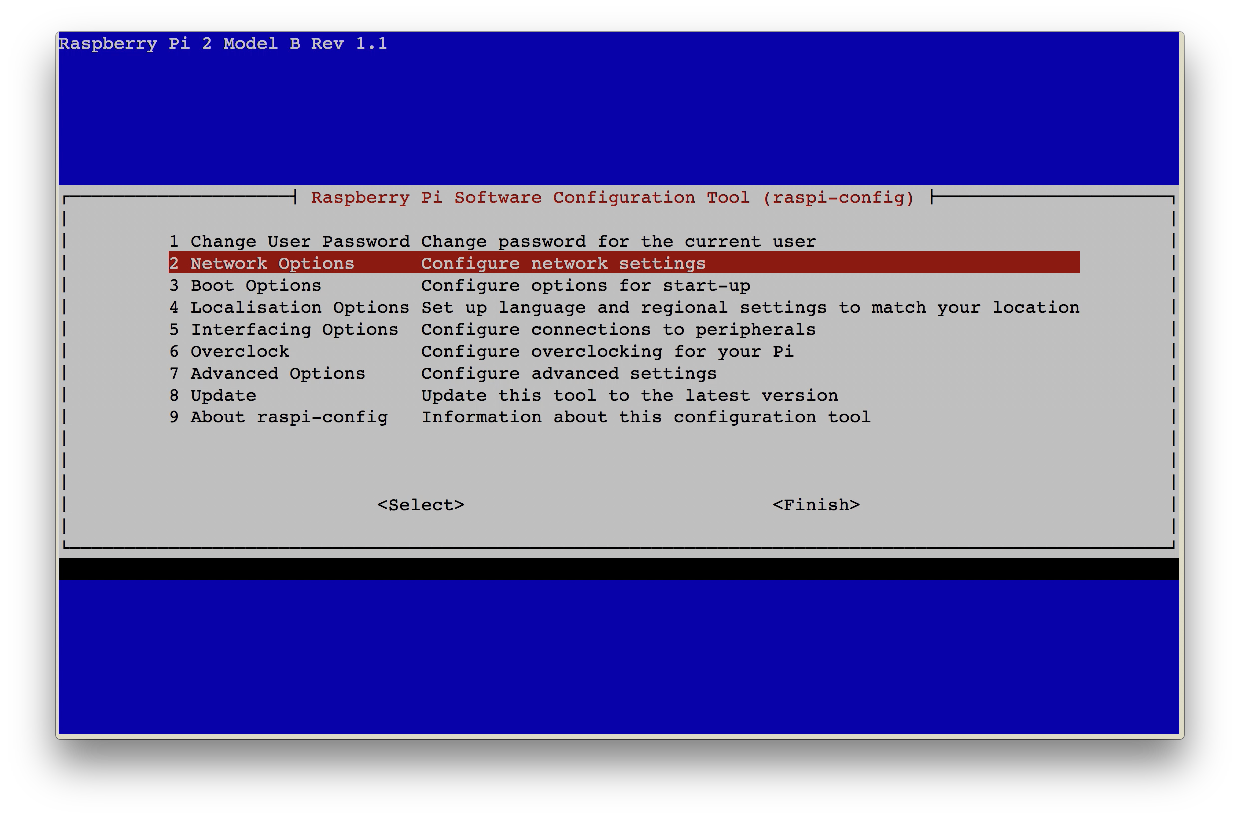
Use your arrow keys to go down to “Network Options” and hit return on your keyboard.
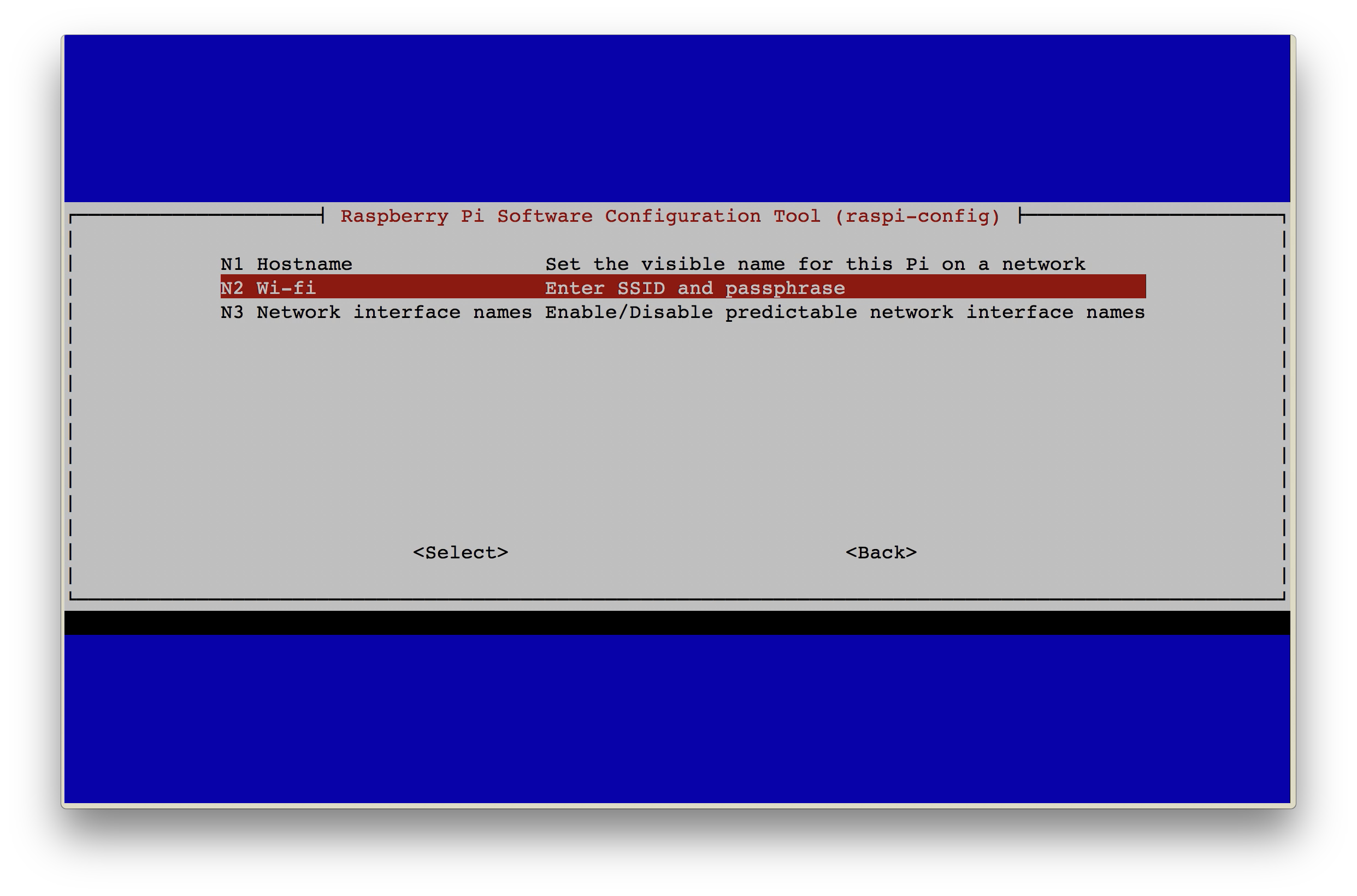
Use the down arrow to highlight “Wi-fi” and then hit the return key on your keyboard.
It will then ask for your wifi network name known as a SSID. Type in your network name and hit return on your keyboard.
Next it asks for your wifi password. Type that in and hit return on your keyboard.
If you are putting your map at work, or at your hangar, or in a pilot lounge you’ll need to repeat these steps to add in that wifi network so your Pi will be able to connect and get weather when you get it hung up in its permanent location.
Then hit the right arrow on your keyboard which should drop you down to the bottom line highlighting the word “Select” use your right arrow one more time to go over to choose “Finish” then click return on your keyboard.
Now it’s time to shutdown your Pi
Type the following to shutdown the pi….
sudo shutdown -h now
Wiring Guide
Directions of what was covered in the video
Next grab your
-
- Breadboard
-
- jumper wires
-
- LED string
-
- Diode
-
- 5V power supply
- Keyboard
Wire everything up using this wiring diagram. Notice that the Data wire on your LED string is actually the middle wire.
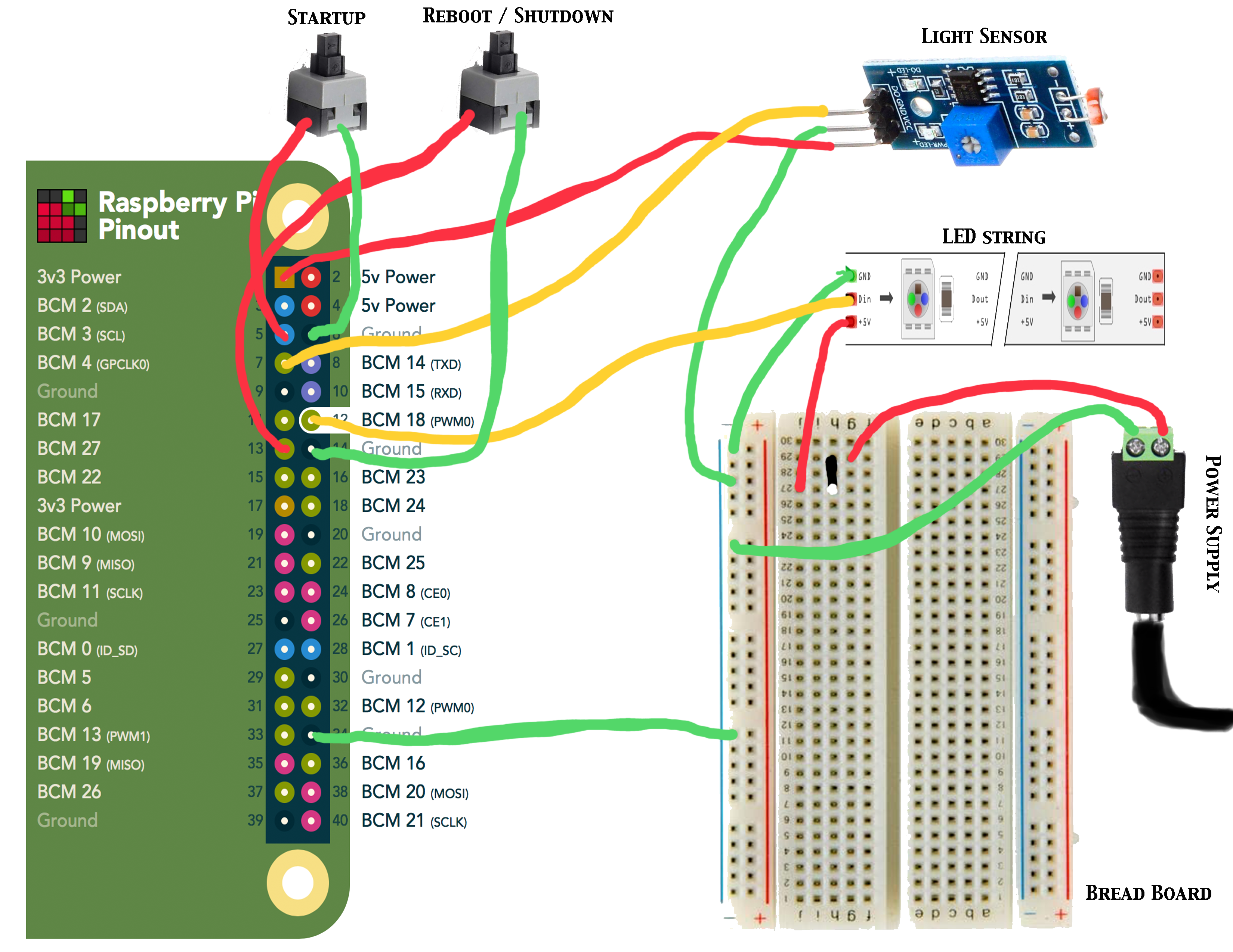
Source: https://pinout.xyz/pinout/pin12_gpio18
Don’t plug the power in until we are done wiring everything up. Start with the power plug end. Take a red male to male jumper wire and leave the male pin end of the wire in tact. Put that into the positive port on the power plug and screw it down tight.
Do the same thing with a dark colored jumper wire.
Plug the dark wire into the breadboard into one of the outer edge holes labeled as ground.
Plug the red wire into one of the inner lateral rows.
Take your 1N4001G Diode and plug the non white strip end into the same lateral row as your red jumper wire. Plug the other end into a different lateral row.
The LED string has a beginning end and a ending end. Power can be applied to either end of of the string, but the data must be plugged into the beginning end. Some LED strings have an arrow on the microchip inside the LED housing that points towards the light. The wires that go in on that side of the microchip would be the in or beginning wires. For the LEDs in the shopping list above you’ll want to use the end that allows a male jumper cable to be plugged into the female end of the string.
So take a red male to male jumper wire and connect the red wire from the LEDs by plugging the male end into the end of the connector, just be sure its lining up with the red wire. Plug the other male end into the breadboard into the same lateral row as the white stripe end of the diode.
Do the same thing with a dark colored jumper wire for the ground and plug that into the same edge row as your ground power jumper.
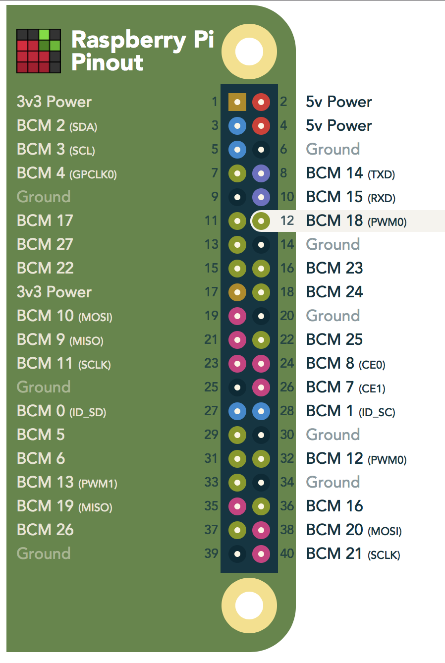
Now take a female to male jumper wire and plug the male end into the middle (data) wire on the LED connector. The other end plugs into pin number 12 on the pi. This is the outermost row of pins on the pi. Count from right to left and plug it on to the 6th pin on the outer row, this is pin number 12 if you are counting both the inner and outer rows.
Light Sensor wiring
Next take a red female to female jumper wire and plug it in to the VCC pin on the light sensor, and plug the other end into the 1st pin on the pi, this would be the one on the end and on the inside row. See the pin out graphic above to verify.
Next take another female to female jumper wire and plug it into the middle pin GND pin on the light sensor, plug this into the outer row on the bread board to aline with the other ground wires.
Finally take another female to female jumper wire and plug it into the DO (data out) pin on the light sensor, and plug the other end into pin 7 on the raspberry pi, this is on the inner row as well, the 4th pin from the end.
Shutdown and Restart Button wiring
Plug the wires from the first button into pins 5 and 6 on the pi. This will be the third from the end. This button will handle the power on function if the pi was shutdown with the other button or with the sudo shutdown -h now command.
Plug the wires from the second button into pins 13 and 14 on the pi. This will handle the reboot / shutdown commands based on how long you hold the button down. Three seconds will initiate a reboot and six seconds will shut the pi down.
If you are using a Raspberry Pi 2 take a male to female jumper wire and plug pin number 4 (second from the right outer row pin) and plug that into the same inner row on the breadboard inline with the red wire from the power cord and the non white strip end of the diode. This will power the Pi without the need for its own power supply.
If you are using a Raspbery Pi 3 or newer you’ll need to use the power supply that shipped with the pi as they are more finicky with their power intake.
Finally plug a male to female jumper wire into pin 34 on the pi, this is pin 4 from the other end of the pins on the outer row. Plug the other end into the ground row on the breadboard. This is very important as the lights won’t work properly if the pi isn’t grounded to the breadboard.
Once it is wired up, plug in the power supply to the little power plug end you used in the wiring. (If using a Pi3B+ also plug in its power supply) It takes about 30 seconds or so for the Pi to boot up.
Once you get to the command line prompt you’ll need to start the script running. Type the following command.
sudo bash /NeoSectional/startup.sh
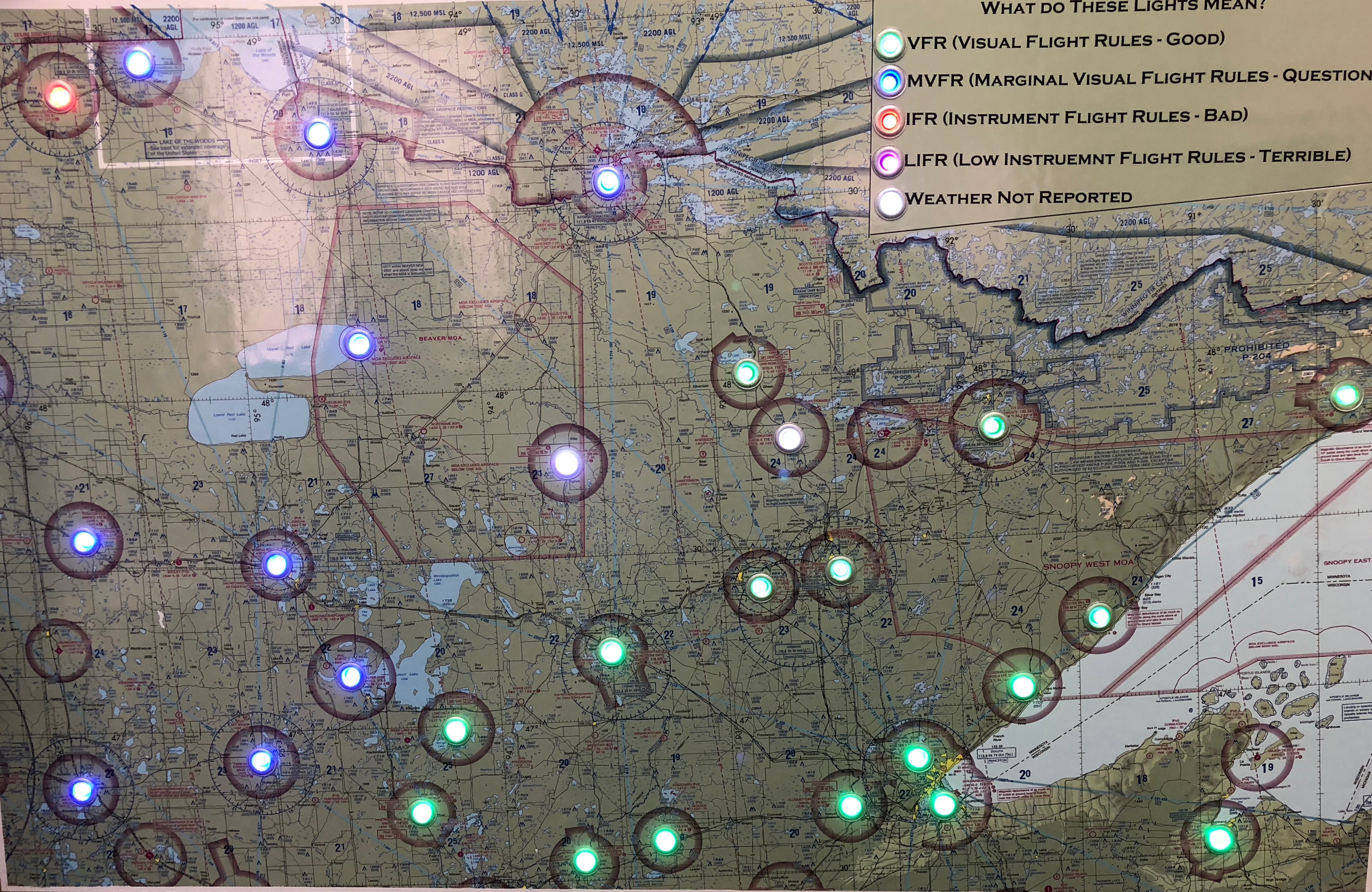
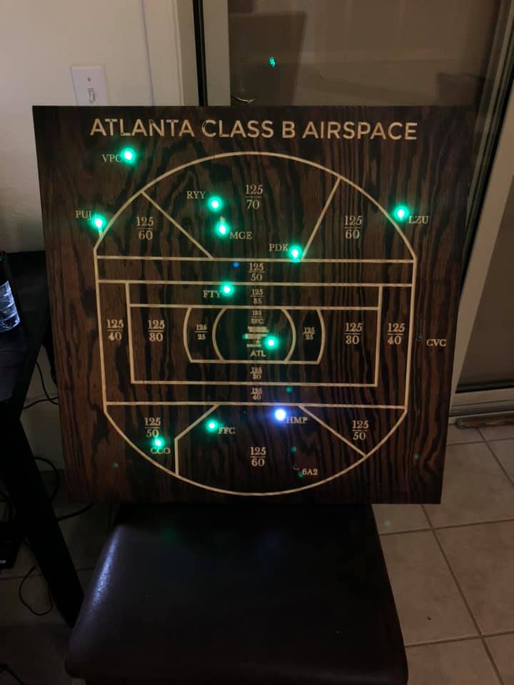
You should see the first 26 (Thats how many are coded in the based image) of your LED’s all turn on for about 30-45 seconds. Then they should all go blank and refresh with the colors of the Metars. (Green, Blue, Red, Pink, and White)
Cover your Light Sensor with your hand and you should see the LED’s dim.
You can choose to test out your buttons at this time if you’d like as well. Remember 3 seconds on the second button will reboot the pi, 6 seconds will shut it down. If the pi has been shutdown with the that button, you can turn it back on by a push of the first button.
Once it has booted up and your LED’s are all working use the second button and shut down the pi or use the keyboard to type the following to shut your Pi down.
sudo shutdown -h now
Hit the return key on your keyboard
Your test of the hardware is now done and you can continue with the build and programing detailed out below.
Step 2: Getting the Map On the Board and Board Preparation
You’ll need to get a hold of a sectional of the area you want to display. I had to splice two sectionals (which I downloaded from the FAA database linked above) together using photoshop. It was a little tricky as I had to rotate one of them to line up correctly since I am printing on a flat map. I then printed the map out on a large format (poster type) printer that uses a roll of paper. You can bring the file to your local kinkos or similar shop to have them print it for you.
Stop by your hardware / lumber store and get a piece of ¾” particle board big enough for your map to fit on it with some room around the edge for your frame to nail to.
Also pick up a can of 3M Spray Glue, and a pack of ⅜” grommets (optional).
I used masking or blue painters tape to hold down half of the map while I rolled back the other half to apply the glue. You need to spay this on both the map back and on the board, then let it sit open for about a minute then lay down that half of the map onto the board. I used a piece of PVC pipe to roll out the air bubbles from the middle to the edges. Then tape down the edges of the side you’ve just glued down and repeat the process on the other half of the map. I let this sit overnight to get good and dry.
Next I used a leather hole punch (that had a smaller diameter than the grommets flange I was planning to use) to cut out a circle around each airport I was planning on using in the project. This made a clean cut and allowed me to peel out the little circles of the map exposing the wood below. You can use a knife point or a finishing nail, tweezers ,etc to get the edge to start to peel. Then just just grab it with your fingers and they come up pretty easily.
Now you can take punch or nail and make a dent in the center of each one to help the drill bit stay centered. Follow that up by drilling holes all the way through the board using a drill bit. I used one just smaller than ⅜” so that the flange of the grommet would overlap the hole, but I found one that allowed the grommet to fit snugly in the hole.
Finally install the grommets. I spray painted the brass ones I found at the hardware store with silver spray paint. I thought that looked better. After they dry, push them into the holes. I had to use a piece of cardboard and a wood block and a hammer to punch them into place. The piece of cardboard helped protect the painted finish.
Use the 1×2 pine boards with some wood glue to frame in the back of the board. This creates space for the LED’s, the PI, and the Breadboard to be glued to the back of the board and the framing will rest against the wall instead of on the lights and the pi. The picture below of the back of my board shows this.
You will need to cut a notch in one edge for the power cord to pass through to an outlet, unless you can wire an outlet in the wall behind where your map will be hung.
The LED’s come coated in a rubber material that makes them waterproof. I wasn’t concerned about liquid and was more concerned about having a smaller diameter that would allow me to use a single sized hole in the wood. I used a utility knife to slit down the edge and peel the rubber off the LED. This made them a smaller diameter which was just a bit smaller than the inset portion of the grommet.
The LED’s have three wires, a hot, a ground, and a data wire. The LED’s I have linked above make it pretty clear with the color of the wires.
The string of LED’s also have a beginning and and end. You want to start on the end that has the female connector on it. The first light is light number 0. So the string of 50 is actually lights 0 – 49. This is important when you get the programming portion of things.
Each light can be cut off the string and wired back together, so you have a couple of options. You could cut all the lights apart, glue them in the holes and the wire them all back together. The other option (which I did) is to keep them in the string and then just skip over lights as needed to make the gap between holes.
I ended up needing two strings of lights to get all of the holes covered since I had to skip so many making the span across the back of the board. You can see this in the picture below. The lights that aren’t in use are not lit up and are just layed out on the back of the board. The ones in use are hot glued into the holes.
I laid the board on a table and then pushed the LED’s into the hole until they wouldn’t go any further pushing up against the table under the board. Then I used a hot glue gun to secure them into place.
Finally I used a sharpie and labeled on the back of the board next to each light with the airport identifier and the number LED it was in the string. This helps out in the programming in the next step.
Step 3: Configuring the Scripts for your Airports
Here are some things we need to know to get started.
-
- How many lights are you using all together, count both ones that will be represented by airports as well as ones that will be behind the board and not in use because of hole spacing. Basically how many LED’s total are there in your strings.
- Are you going to have a map legend like I have in my live sectional? If so we need to know what number LED’s those are in the string. Remember the first LED is number 0.
- You have the potential for the following Legend Itmes
- VFR
- MVFR
- IFR
- LIFR
- High Wind (user defined)
- Lightning
- No Weather Reported
- You have the potential for the following Legend Itmes
Here is a video walking you through all the programming stuff detailed below.
Take your Pi and plug it back into your TV or Monitor with an HDMI port. Also plug in your keyboard and then plug it into power.
Next let’s get your airports into the script. Type the following into the command line…
sudo nano /NeoSectional/airports
Hit return on your keyboard.
A list of airports, NULL, and LGND will show up on your screen.
You need to use the arrow keys to move around in this file. Use the down arrow to get to the bottom of the list and then delete all of the airports and Nulls.
When you get to the top of the list it’s time to start listing the airports you’ll be using. Make sure you use the full FAA airport identifier. Ie. Duluth airport in Minnesota should be KDLH not just DLH. If you are doing Alaska airports be sure to use the PA format like PAOR or PAFA, PAVD. I have noticed this script sometimes has troubles with airports like 4R5 and have now figured out what the issue is. For airports like 4R5 you need to put them in as K4R5. Not sure what’s up with that. Anyway look at the back of your board with the glued in LED’s that are numbered for you and start typing them in the file like follows. Where the legend lights are you need to type in LGND.
KORB
KCQM
NULL
NULL
KELO
NULL
NULL
KTWM
KDLH
KSUW
LGND
LGND
LGND
Important: make sure your list of airports doesn’t end in a NULL this will cause the script to fail. This was pointed out by Mark who was kind enough to really help move this project forward.
Just for reference KINL would be light 0 or the first light on my string. It is followed by light 2 glued into KCQM. That is followed by two lights not being used, and then light number 5 which would be glued into KELO.
Fill out the entire list with the airport codes, LGND and NULL as necessary.
If you are using a map legend type those lights in with Green, Blue, Red, Pink, White, and potentially blinking. You need to remember what numbers each of these are for another part of the script.
When you get all the airports, LGND and NULL listed out hit the following keys on your keyboard.
control and x
(this tells the pi to close the file)
Then type y and hit the return key on your keyboard. (This tells it to save the file)
Next let’s make sure the script is set up correctly for you.
In the command line type the following…
sudo nano /NeoSectional/metar.py
Using the arrow keys again go to the area designated as the “User defined area” and change the LED count to the number of LED’s you are using in your entire project both the null LED’s and the ones representing airports and legends.
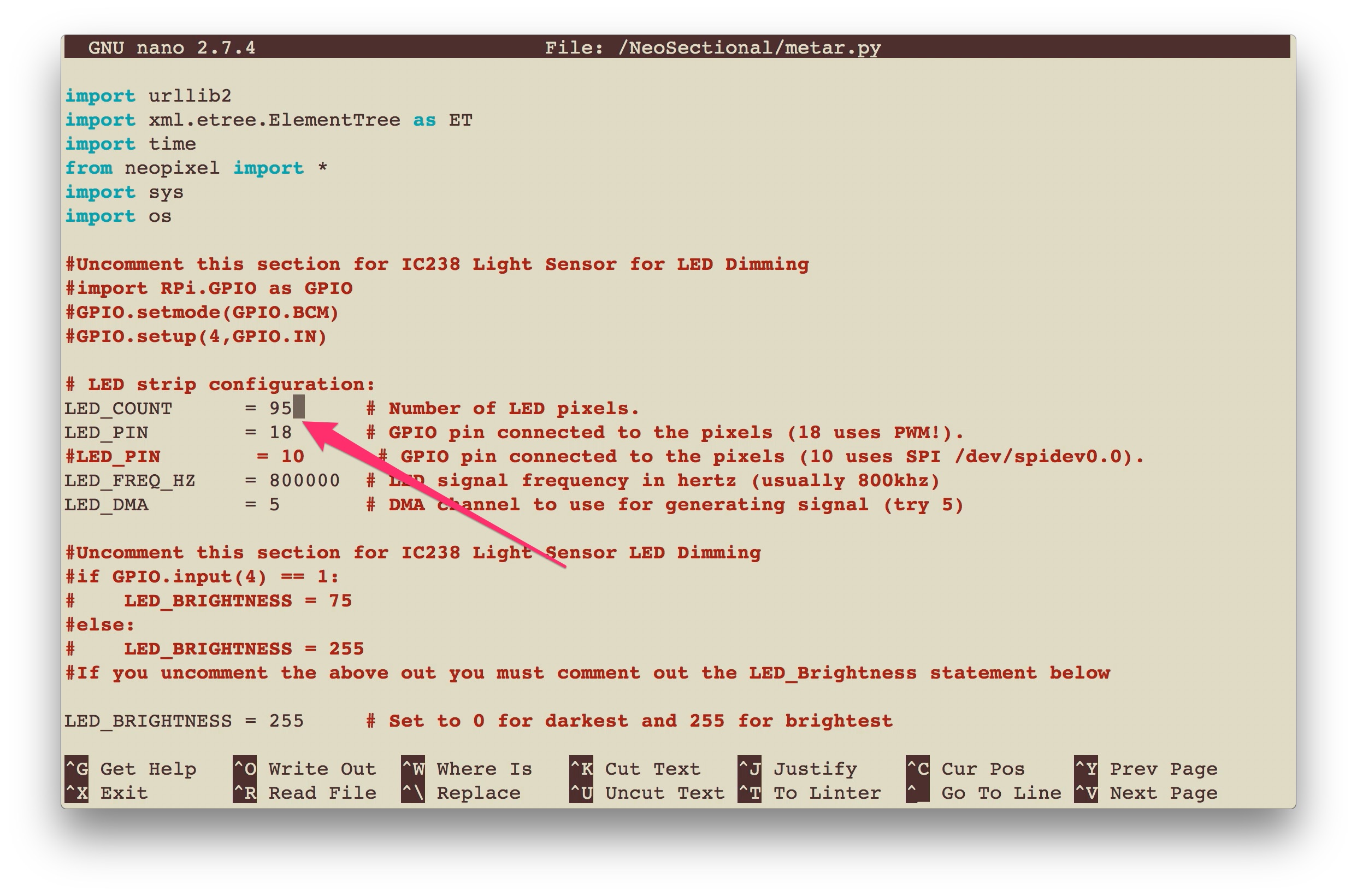
You need to change the areas that talk about map legend and wind speed threshold. This is where you can disable the map legend, or if defined the lights numbers you are using for your legend.
To change the refresh rate find that user defined setting and change it to your liking. One thing I need to test out is to see if the FAA has a refresh threshold. I was working on this script at work one day a couple weeks ago and all of a sudden nothing was working. I think I may have been blocked by the FAA weather server. I had to wait a day before it would start working again off of my work IP address. I was able to access it if I used my phones hotspot. I’ll see if I can figure out what their magic time is.
Once you have addressed all the user defined areas type the following on your keyboard.
control x
Type y then hit the return key.
Next you need to make some similar settings to allow the lights to shutoff when you turn off the pi.
sudo nano /NeoSectional/shutoff.py
Update this with your number of LEDs
control x
Type y then hit the return key.
Next we need to set up the script to launch when the pi is started up. This way anytime it gets booted up it will run on its own.
To do this edit a page by doing the following.
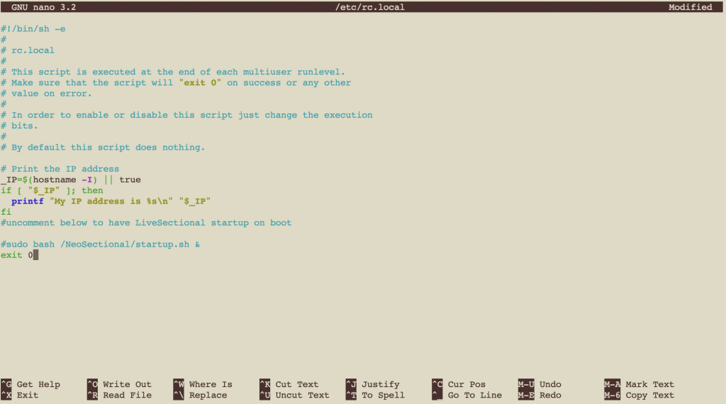
sudo nano /etc/rc.local
Uncomment (remove the # from the beginning of the line) for the line that says
#sudo bash /NeoSectional/startup.sh &
Once you have done this save the file by typing the following….
control x
Type y then hit the return key.
You can now shut down your PI by typing the following…
sudo shutdown -h now
It is now safe to unplug the power cord, keyboard, and hdmi cable from the pi and bring it back over to your map board.
Step 4: Wiring Everything Up
Follow the same wiring steps provided earlier when you attach your Raspberry Pi and your Breadboard to the back of your map.
Use your hot glue gun again to glue down the breadboard, the pi, and the little end of the power cord.
Once that sets up you are done!!!
Plug in the power and watch it boot up.
It will start out by turning all of the lights a white or rainbow color as it pulls down the weather for all of your airports. It will then refresh them all displaying the correct colors for the current weather at each airport.
To turn off the “rainbow” colors during refresh you can do so by editing the startup.sh file.
sudo nano /NeoSectional/startup.sh
This turns off the test portion and just runs the weather script.
put a # in front of the
sudo python /NeoSectional/test.py
The script is set up to refresh every 15 minutes. Often time the first time it boots up it refreshes a few minutes after the first display of weather colors. Then falls into its 15 min refresh cycle.
Finally frame in the front of the board to finish the project.
Enjoy
If you feel like throwing a couple dollars my way I wouldn’t be opposed. 🙂 paypal.me/WilliamBrysonIII
This is a great project and very helpful walkthrough. I did a huge 8×4 map based on this with 101 LEDs. Works pretty well, however I have a few airports that are not reporting on here, but they report on foreflight and other aviation apps. My home airport is one in particular (KAPS). Any insight?? Again awesome tutorial and explanation.
How did you string all your set of lights together? Was it as simple as connecting the male to female? My 2nd strand isn’t talking
Hi Glenn,
I was able to just connect the end of the first with the beginning of the second. If you think there is a problem with the connectors, you can cut them off and solder each wire together individually.
Hope this helps,
Bill
I like to concept and have been building one myself but the code you provided is having issues with my Raspberry Pi. I would like to discuss with you some of the challenges and see what type of hardware you used. Please contact me at duax@Comcast.net. Thank you, Brett.
Hello,
I’m following through your instructions, but etcher is telling me that the image file is 15.52GB. You mentioned above that it now supports 8GB SD cards. Any ideas what a solution to this might be?
Have you tried recently? Are you still having problems with this?
When trying to modify the airports I get a ‘/NeoSectional/airports’ is unwritable. Any ideas?
try sudo nano /NeoSectional/airports
Type the following command at the prompt:
sudo chmod a+w /NeoSectional/airports
This changes owner permissions
HI Bill,
Great walk through, I am just about to start making this. I have a question before i begin though. THe Metars I want are in Ireland and the UK. Will the steps be the same for pulling the metars? Do i just change the airport icao names i mean. for example Donegal airport in Ireland ie EIDL.
thanks
I see the note at the top about an update, was that done? I’m interested in starting one of these this fall, thanks!
Hi Jim,
I am hoping to release the 2.0 version by the end of the week. We are still running it through its paces and there are a couple of small details that aren’t mission critical, but would make it a more streamlined product that I’d like to get figured out in the code. I can send you the beta version of the code if you want to jump right in. It seems very stable and I haven’t had any negative feedback from the few people that are helping me test it out. Other wise I will have it out in the next few days for the official release.
Also if you wouldn’t mind sending me a picture of your finished product to put on this site, I’d really appreciate it.
Thanks,
Bill
Installed version 2 on my Rpi and have yet to get it working.
Version 1 has been running for several months.
Keep running into the below error;
Updating FAA Weather Data
Traceback (most recent call last):
File “/NeoSectional/metar.py”, line 139, in
root = ET.fromstring(content)
NameError: name ‘content’ is not defined
Thanks,
Don Jennings
Bill, I did get the Live Sectional map to work.
Looks like I was having a WIFI issue.
I ended up having to reboot my router and also drop a “ssh” file into my boot directory.
Looks like SSH is disabled, by default, in the Rpi now. Dropping a SSH file into the boot directory enables it.
On another note, I have commented out /NeoSectional/test.py in the startup.sh but still have the rainbow effect when I run startup.sh.
Thanks !!!
Hi Don,
Can you send me an email with some screen shots of your startup.sh file?
hilts50 (at) g mail
This is pretty cool but a lot of work to build. Have you considered making these for FBOs and other folks and selling them?
I would like to build this but with something a little more permanent than the breadboard – would this work:https://www.tindie.com/products/ManiacalLabs/pipixel-raspberry-pi-led-strip-hat/
Hi Laup,
Yes any board that will allow you to solder the components together will work just fine.
How do you stop the raspberry pi process once you’ve set it up? I want to update the airport coding and control X doesn’t stop the program.
Hi Kenneth,
Try – Ctrl + Alt + F2 This should stop the script and bring you back to the command prompt.
V3 will be released in about a week and will make changes like this a breeze.
Let me know if you need any more assistance.
Bill
This project has been amazing. I am done with everything except the light sensor.
Just curious how you mount the light sensor to make it look good – i.e. so it doesn’t show the electronics but still functions well. I’m thinking about tucking it in to a corner so it’s not so obvious.
The only part of the light sensor that needs to be visible is the little ball that extrudes from the end of the chip. You could use a chisel or a hand router to notch out a part for the board to be embedded in the frame with just the sensor portion protruding above the frame surface up against the wall. This would provide a very low profile.
Thoughts?
Bill
Almost finished with this project. Ended up getting a little drill happy and making more airports than 100 so I am waiting on my last string of LEDs to be delivered. This is a neat project and the one person who sells them was going to make me wait 2.5 months to receive it. I got this done in a weekend. This tutorial makes the lights and computer part super easy…the actual map, foam board, and gluing the lights in is a very tedious process.
What happens if I decide to remove the buttons and light sensor from the project without changing any programming?
Everything will work just fine without either being connected. Please send a picture of your finished project I’d love to add it to the site.
Be sure to check out V3 when we release it in about a week.
Bill
I would like to begin planning which airports I will use.
Is there a list of airports? Or; which website is the program querying for weather data?
You can check airports at https://www.aviationweather.gov/ Hope this helps.
Bill
Thanks for the project! I have built all of the electronics and am finishing the board. In the process, I ported the code to Python3 and fixed a few bugs (including the ending in NULL crash.) I’d love to upload the code to you.
Bill,
LiveSectional is pretty cool. First I should tell you that I am not a programmer. I am a hardware guy but software eludes me. I built a frame and downloaded Phjill Sling’s version but struggled for weeks and could never get it up and running automatically. So I downloaded your software V2.o. I am running it off a pi ZERO. Have a HDMI monitor and usb keyboard for fine tuning it. (100 LED’s)I have it up and running. It seems to run perfectly with the monitor connected. The problem is when I disconnect the monitor and reboot. (disconnect the power) The Rainbow test from “metar.py” (at least that where I think its coming from) does lots of funky LED flashing then just flashes LED’s in what appears a random pattern indefinitely . As soon as I plug in the monitor into the pi it works just fine.
I did disable the test.py script in Startup.sh, made no difference. I do not have the pushbuttons or light sensors installed. The pi is grounded to the LED’s .
Do you have any ideas ? I would be happy to send whatever you need.
Regards Bob
This sounds like it may be grounding issue. We are about to release V3 as well that may help you set things up more efficiently.
Let me know if you need more help.
Bill
Hello, thanks for providing this guide. I am getting an error on startup: ValueError: invalid literal for int() with base 10: ”
Bill,
I have it up and seems to be operating . My question is if you reboot or shut it down with the buttons, do you have to hook keyboard and monitor back up to give it the start up command?
It isn’t taking off on its own with the start up button.
Thanks for your time
Craig
It sounds like auto run isn’t currently enabled on your system. If you update your system to run V3 which is due out later this week you can make these changes very easily.
Bill
The converter/power supply is out of stock. They are offering instead a ALITOVE 30W Universal AC to DC Power Supply Adapter 3V 4.5V 5V 6V 7.5V 9V 12V Adjustable with 6 Adapter Tips…
I don’t think this would matter.. Thoughts?
My son and I are building one of these now. Thanks for paving the road for us.
Is it possible to build this with only one power supply? It is a bit cumbersome to have 2.
I know you briefly mentioned that the power supply for the Pi is temperamental.
Is it not possible to get 5V from the breadboard for the lights or is that not powerful enough?
You should be able to power the pi off of the bread board. I’ve noticed that the Pi3B+ and the 4B are pretty finicky on power, and sometimes having the displayed connected impacts things as well, your milage may vary.
Let me know if you need further assistance.
Bill
I built mine without the power/reboot switches or light sensor on a Pi Zero W. The only connections I made were the pos, neg, data wires directly to the Pi and only use the single power supply to the Pi. You might need the second one for the Pi 3+
Took me about a day and fully built it but having some issues now that I programed the airports. I got the rainbow effect and it started running the script on bootup with no end in sight. What do I do to resolve this issue. Please email me at rcarr90@gmail.com
Hi, thanks for the walkthrough.
Question… I have “commented out” the sudo python /NeoSectional/test.py section of the startup.sh file and the rainbow effect is still happening.
My startup.sh file looks like this:
#sudo python /NeoSectional/test.py
sudo python /NeoSectional/metar.py
Terminal only Mac is even color coding that line as a comment. Is there another place this needs to be edited?
Hi Brian,
We are about to release Version 3 which gives you an easy way to make this edit. Please stay tuned for this release.
Thanks,
Bill
Bill,
Tried to make mine with a Zero (lower profile for the frame)(using a power supply module and level shifter), but no luck. Swapped the Zero for a 3 and worked like a charm. Any thoughts?
Try V3 that was just released. http://www.livesectional.com